LED Matrix Display
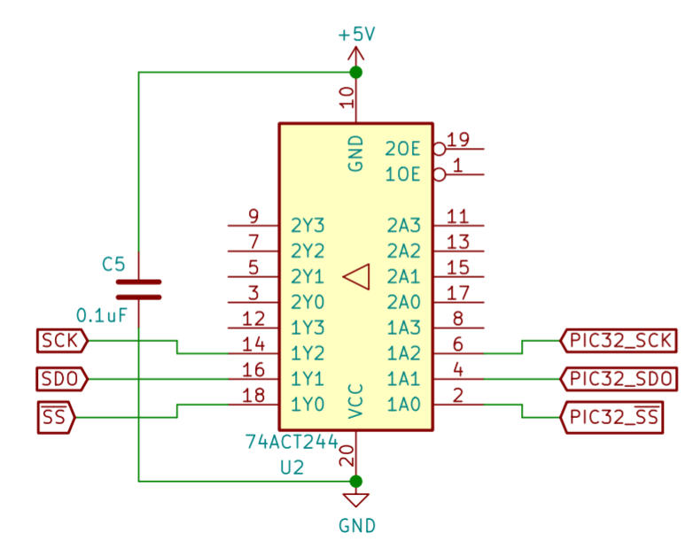
An LED Matrix was controlled by the PIC32 microcontroller via SPI with a line driver stepping up 3V logic from the microcontroller to 5V logic to drive the LED Matrix. Control of Output Enabled Inputs was found to be unnecessary and so is omitted in the schematic.
An LED Matrix was controlled by the PIC32 microcontroller via SPI with a line driver stepping up 3V logic from the microcontroller to 5V logic to drive the LED Matrix. Control of Output Enabled Inputs was found to be unnecessary and so is omitted in the schematic.
Steering Wheel
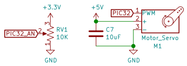
The steering wheel rotation state was read from the analog ADC input corresponding to a 10k rotary potentiometer. The servo to indicate the current car direction was controlled via PWM.
The steering wheel rotation state was read from the analog ADC input corresponding to a 10k rotary potentiometer. The servo to indicate the current car direction was controlled via PWM.
IR Target Practice
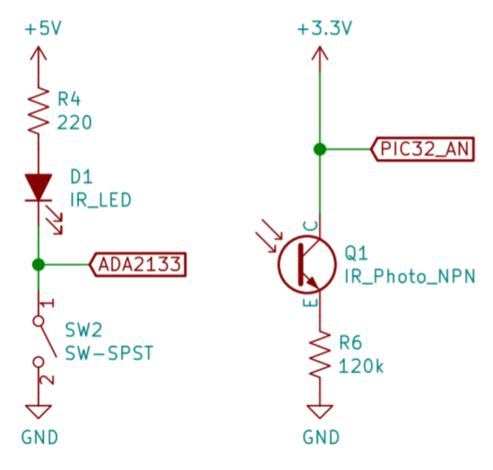
An IR emitter (gun) could be turned on using a simple metal contact trigger. The IR phototransistor (target) could then be read directly as an analog ADC input. High pull-down resistor values were chosen to increase sensitivity. The need for a hardware-based Schmitt trigger was circumvented by tuning a simple software threshold and state machine changes that ignored high variance inputs.
An IR emitter (gun) could be turned on using a simple metal contact trigger. The IR phototransistor (target) could then be read directly as an analog ADC input. High pull-down resistor values were chosen to increase sensitivity. The need for a hardware-based Schmitt trigger was circumvented by tuning a simple software threshold and state machine changes that ignored high variance inputs.
Gear Shift
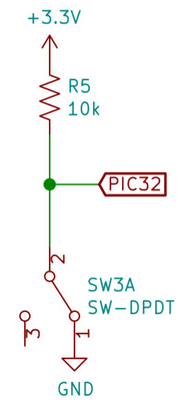
The gear shift consisted of a simple switch and pull-up resistor mechanism.
The gear shift consisted of a simple switch and pull-up resistor mechanism.
LED Indicators
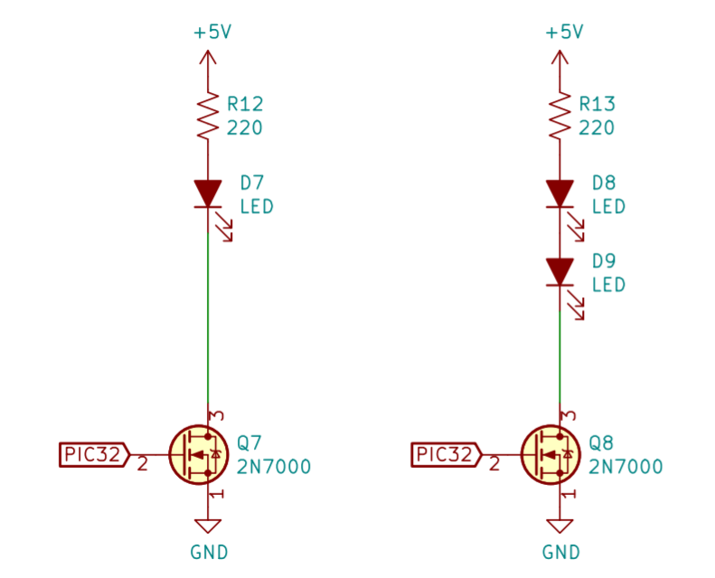
The LED indicators for indicating the target direction and the need to gear shift consisted of a LED and series resistor toggled with a NMOS transistor. The LED “eyes” of the target consisted of a similar circuit with two LEDs in series.
The LED indicators for indicating the target direction and the need to gear shift consisted of a LED and series resistor toggled with a NMOS transistor. The LED “eyes” of the target consisted of a similar circuit with two LEDs in series.
Audio Module
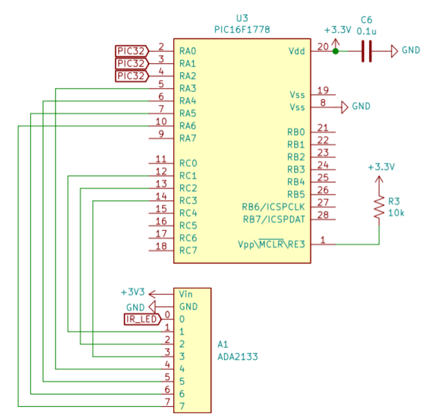
A PIC16 microcontroller was programmed to continuously read 3 PIC32 inputs and drive 7 lines on the ADA2133 audio module, essentially acting as a decoder. The “8th” state drives all lines high, muting all sounds.
A PIC16 microcontroller was programmed to continuously read 3 PIC32 inputs and drive 7 lines on the ADA2133 audio module, essentially acting as a decoder. The “8th” state drives all lines high, muting all sounds.
Overall Schematic
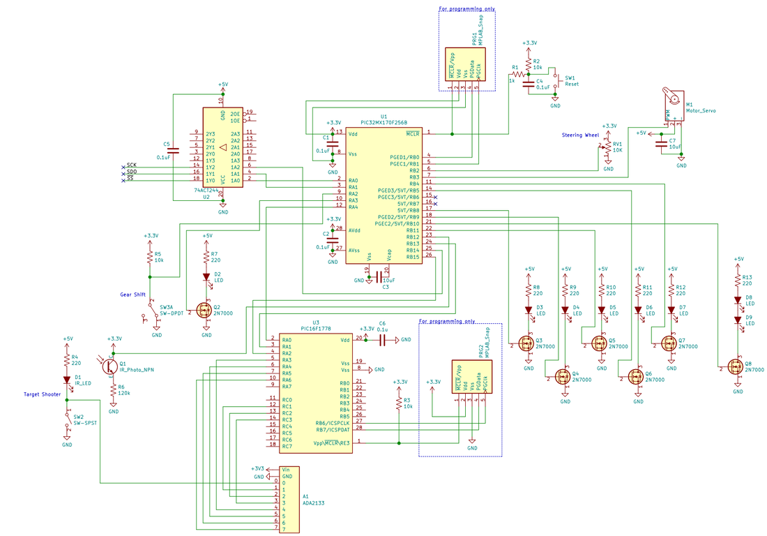
Our final schematic with all subcomponents is below. Download the attached pdf file for higher resolution.
Our final schematic with all subcomponents is below. Download the attached pdf file for higher resolution.
| schematic.pdf | |
| File Size: | 68 kb |
| File Type: | |
